
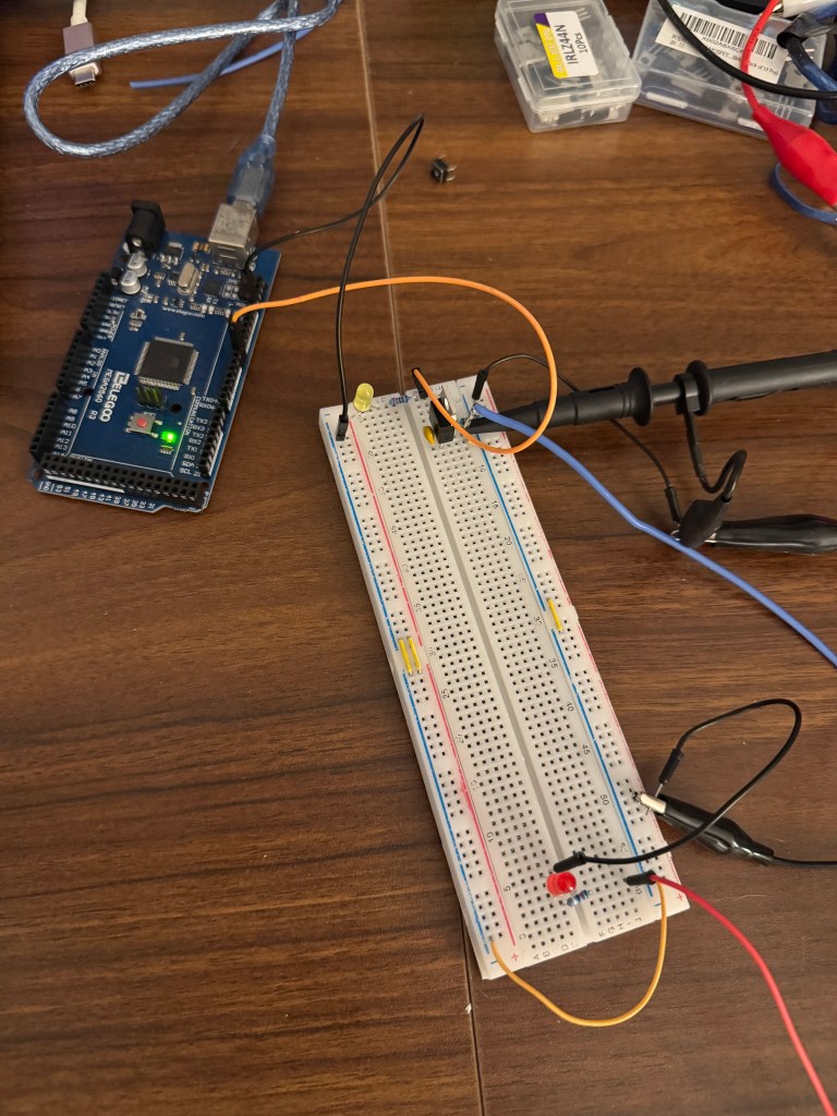
Today, I built the charging circuit’s switch. My sorting cabinet is still on its way. For now, I have to deal with this mess, not ideal when I’m working on high voltage. I’m constantly on my nerves for fear of anything shorts.
I decide not to use a mechanical button so fewer things that can go wrong. The Arduino script here reads commands from serial monitor.
/*----------------------------------------------------------------------------
 * Serial‑controlled PWM on pin 7
 * --------------------------------------------------
 * Baud rate : 115 200
 * Commands  :
 *   c   → set pin HIGH  (LED on)
 *   c0  → set pin LOW   (LED off)
 *
 * Any other input triggers a warning.
 *---------------------------------------------------------------------------*/

const byte PWM_PIN = 7;                 // digital‑7 (may be PWM‑capable)

// Keep an explicit list of recognised commands (helps with maintenance / help)
const char *KNOWN_COMMANDS[] = {"c", "c0"};
const byte  NUM_COMMANDS     = sizeof(KNOWN_COMMANDS) / sizeof(KNOWN_COMMANDS[0]);

void printHelp()
{
  Serial.println(F("Available commands:"));
  for (byte i = 0; i < NUM_COMMANDS; ++i) {
    Serial.println(F("  » " ));
    Serial.println(KNOWN_COMMANDS[i]);
  }
  Serial.println();
}

void setup()
{
  pinMode(PWM_PIN, OUTPUT);
  digitalWrite(PWM_PIN, LOW);           // start safe (OFF)

  pinMode(LED_BUILTIN, OUTPUT);
  digitalWrite(LED_BUILTIN, LOW);

  Serial.begin(115200);
  while (!Serial) { /* wait for native USB boards */ }

  Serial.println(F("\nSerial‑controlled PWM ready."));
  printHelp();
}

void handleCommand(const String &cmd)
{
  if (cmd == "c") {
    digitalWrite(PWM_PIN, HIGH);
    digitalWrite(LED_BUILTIN, HIGH);
    Serial.println(F("PWM 7 → HIGH"));
  }
  else if (cmd == "c0") {
    digitalWrite(PWM_PIN, LOW);
    digitalWrite(LED_BUILTIN, LOW);
    Serial.println(F("PWM 7 → LOW"));
  }
  else {
    Serial.print(F("Unknown command: '"));
    Serial.print(cmd);
    Serial.println(F("'"));
  }
}

void loop()
{
  if (Serial.available()) {
    String cmd = Serial.readStringUntil('\n'); // read until newline (Enter)
    cmd.trim();                                // strip CR/LF and spaces
    if (cmd.length())                          // ignore empty lines
      handleCommand(cmd);
  }
}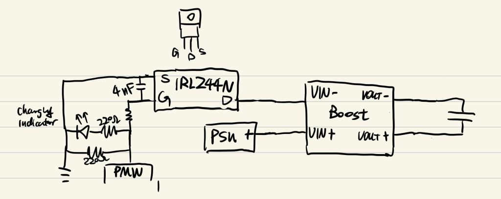
I was interested to see how fast can the charging gatekeeper IRLZ44N turn on. The scope give a 658 ns, which is pretty decent. 0.5–2 µs edges are typical when the GPIO can source/sink only 10–25 mA into a 5–15 nC gate. So, 0.658 µs is on the quicker side—indicates the device isn’t gate-charge-limited here.
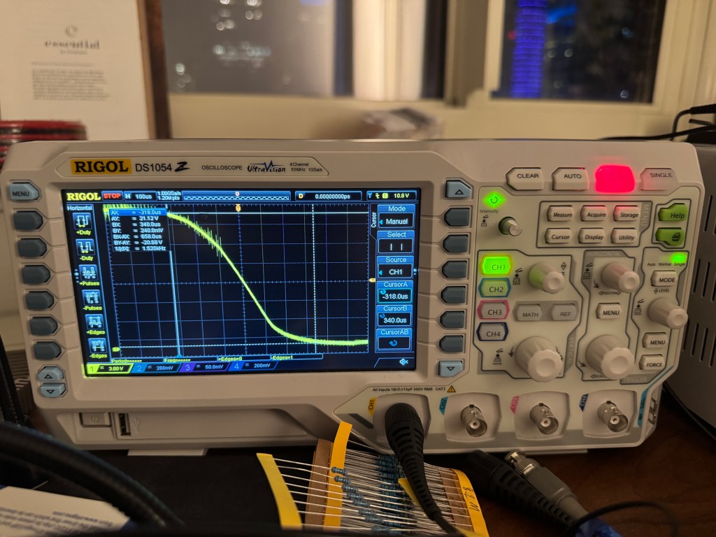
Because I’ve only just started the project. It’s a good sanity check, but this good switch performance might all change when I put in the capacitor.


Leave a comment